Our Gallery
/AVIVAET GATE VIEW.jpg)
/BAMBOO HOUSE WARDHA.JPG)
/MANAGERS QUARTERS AVIVET.jpg)


Contact Info
-
Prasanna Kulkarni
201,Raghukul-9,
Plot no 93 Abhyankarnagar Nagpur -
pvk_7@yahoo.com
Kulkarnidesign@yahoo.com - 0712-3580282, +91 93599 93992
[ what we offer ]
Ultrasound Pulse Velocity Meter Test
The ultrasonic pulse is generated by an electroacoustical transducer. When the pulse is induced into the concrete from a transducer, it undergoes multiple reflections at the boundaries of the different material phases within the concrete. A complex system of stress waves is developed which includes longitudinal (compressional), shear (transverse) and surface (rayleigh) waves. The receiving transducer detects the onset of the longitudinal waves, which is the fastest.
Because the velocity of the pulses is almost independent of the geometry of the material through which they pass and depends only on its elastic properties, pulse velocity method is a convenient technique for investigating structural concrete.
The underlying principle of assessing the quality of concrete is that comparatively higher velocities are obtained when the quality of concrete in terms of density, homogeneity and uniformity is good. In case of poorer quality, lower velocities are obtained. If there is a crack, void or flaw inside the concrete which comes in the way of transmission of the pulses, the pulse strength is attenuated and it passes around the discontinuity, thereby making the path length longer. Consequently, lower velocities are obtained. The actual pulse velocity obtained depends primarily upon the materials and mix proportions of concrete. Density and modulus of elasticity of aggregate also significantly affect the puise velocity.
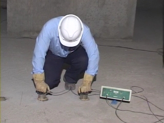
In this test method, the ultrasonic pulse is produced by the transducer which is held in contact with one surface of the concrete member under test. After traversing a known path length L in the concrete, the pulse of vibrations is converted into an electrical signal by the second transducer held in contact with the other surface of the concrete member and an electronic timing circuit enables the transit time (T) of the pulse to be measured. The pulse velocity (V) is given by: V = L/T
Once the ultrasonic pulse impinges on the surface of the material, the maximum energy is propagated at right angles to the face of the transmitting transducer and best results are, therefore, obtained when the receiving transducer is placed on the opposite face of the concrete member (direct transmission or cross probing). However, in many situations two opposite faces of the structural member may not be accessible for measurements. In such cases, the receiving transducer is also placed on the same face of the concrete members (surface probing). Surface probing is not so efficient as cross probing, because the signal produced at the receiving transducer has an amplitude of only 2 to 3 percent of that produced by cross probing and the test results are greatly influenced by the surface layers of concrete which may have different properties from that of concrete inside the structural member. The indirect velocity is invariably lower than the direct velocity on the same concrete element. This difference may vary from 5 to 20 percent depending largely on the quality of the concrete under test. For good quality concrete, a difference of about 0.5 km/ sec may generally be encountered.
To ensure that the ultrasonic pulses generated at the transmitting transducer pass into the concrete and are then detected by the receiving transducer, it is essential that there be adequate acoustical coupling between the concrete and the face of each transducer. Typical couplants are petroleum jelly, grease, liquid soap and kaolin glycerol paste. If there is very rough concrete surface, it is required to smoothen and level an area of the surface where the transducer is to be placed. If it is necessary to work on concrete surfaces formed by other means, -for example trowelling, it is desirable to measure pulse velocity over a longer path length than would normally be used. A minimum path length of 150 mm is recommended for the direct transmission method involving one unmoulded surface and a minimum of 400 mm for the surface probing method along an unmoulded surface.
The natural frequency of transducers should preferably be within the range of 20 to 150 kHz. Generally, high frequency transducers are preferable for short path lengths and low frequency transducers for long path lengths. Transducers with a frequency of 50 to 60 kHz are useful for most all-round applications.
Our Valuable Clients